
IBM PC (and
compatibles) Pin-Outs, Connections and Cables
CONTENTS
Serial Ports
Serial Port Mapping
9-Pin Serial Port
25-Pin Serial Port
Null modem Connections
Serial Loop-back Plugs
Parallel Printer Port
Parallel Printer
Port Mapping
25-Pin Parallel Port
Parallel
Loop-back Plug for Checkit®
Parallel
Loop-back For Norton® Utilities
Parallel
Loop-back For PC-Certify®
Parallel
Transfer Cable for Interlnk
36-Pin Centronics
Printer Port
Power Supply Unit Connectors
AT Motherboard
Power Connectors
Device Power Connectors
Rear Panel Connectors
AT Keyboard Connector
PS/2 Keyboard/Mouse
Connector
PS/2 Mouse
Port to 9-Pin D-Type Adapter
15-Pin Game Connector
MDA and CGA Adapters
EGA Adapter
VGA Adapter
10BaseT Ethernet LAN
T568A RJ45 pin
assignments
T568B RJ45 pin
assignments
Cross-Over
Cable pin assignments
Common Modem to UK Telephone
Socket
Typical
Hayes Compatible Modem Lead
Typical UK
Modem Lead (e.g. Pace)
The IBM PC uses a DTE (Data Terminal Equipment) Connection standard presented on 9 or 25-pin male D-type connectors. Most Modems are DCE (Data Communication Equipment), fitted with 25-pin female D-type sockets.
| COM1: | $3F8-3FF |
| COM2: | $2F8-2FF |
| COM3: | $3E8-3EF |
| COM4: | $2E8-2EF |
| 9-Pin Serial Port | |||||||
|
9-Pin Male D-Type Connector (Figure 1) |
|||||||
|
Pin |
In/Out |
Signal |
Meaning |
Pin |
In/Out |
Signal |
Meaning |
|
1 |
In |
DCD |
Data Carrier Detect |
6 |
In |
DSR |
Data Set Ready |
|
2 |
In |
RD |
Receive Data |
7 |
Out |
RTS |
Request to Send |
|
3 |
Out |
TD |
Transmit Data |
8 |
In |
CTS |
Clear to Send |
|
4 |
Out |
DTR |
Data Terminal Ready |
9 |
In |
RI |
Ring Indicator |
|
5 |
- |
SG |
Signal Ground | ||||

Figure 1
| 25-Pin Serial Port | |||||||
| 25-Pin Male D-Type Connector (figure 2) | |||||||
|
Pin |
In/Out |
Signal |
Meaning |
Pin |
In/Out |
Signal |
Meaning |
|
1 |
- |
FG |
Frame Ground |
14 |
Out |
STD |
{Secondary TD} |
|
2 |
Out |
TD |
Transmit Data |
15 |
In |
TC |
{Transmitter Clock} |
|
3 |
In |
RD |
Received Data |
16 |
In |
SRD |
{Secondary RD} |
|
4 |
Out |
RTS |
Request to Send |
17 |
In |
RC |
{Receiver Clock} |
|
5 |
In |
CTS |
Clear to Send |
18 |
- |
- |
Unassigned |
|
6 |
In |
DSR |
Data Set Ready |
19 |
Out |
SRTS |
{Secondary RTS} |
|
7 |
- |
SG |
Signal Ground |
20 |
Out |
DTR |
Data Terminal Ready |
|
8 |
In |
DCD |
Data Carrier Detect |
21 |
In |
SQ |
{Signal Quality} |
|
9 |
In |
{+ve dc test voltage } |
22 |
In |
RI |
Ring Indicator | |
|
10 |
In |
{-ve dc test voltage} |
23 |
Out |
{Data Rate Selector} | ||
|
11 |
- |
Unassigned |
24 |
Out |
TC |
{External Transmitter Clock} | |
|
12 |
In |
SDCD |
{Secondary DCD} |
25 |
|||
|
13 |
In |
SCTS |
{Secondary CTS} |
Functions in { } are not normally supported. |
|||

Figure 2
| Null modem Connections (All Connectors Female) | ||||||||
|
Signal |
D-25 |
D-9 |
D-25 |
D-9 |
||||
|
SG |
ó |
SG |
7 |
5 |
ó |
7 |
5 |
|
|
TD |
ó |
RD |
2 |
3 |
ó |
3 |
2 |
|
|
RD |
ó |
TD |
3 |
2 |
ó |
2 |
3 |
|
|
RTS |
ó |
CTS |
4 |
7 |
ó |
5 |
8 |
|
|
CTS |
ó |
RTS |
5 |
8 |
ó |
4 |
7 |
|
|
DSR |
ó |
DTR |
6 |
6 |
ó |
20 |
4 |
|
|
DTR |
ó |
DSR |
20 |
4 |
ó |
6 |
6 |
|
|
DCD |
ó |
DCD |
8 |
1 |
ó |
8 |
1 |
|
| Serial
Loop-back Plugs (Female) As used by CheckIt®, PC Certify® and Norton Utilities® etc. |
||||||||||
| Signals to Link | D-25 | D-9 | ||||||||
|
TD |
ó | RD | 2 |
ó |
3 |
3 |
ó |
2 | ||
|
RTS |
ó | CTS | 4 |
ó |
5 |
7 |
ó |
8 | ||
|
DSR |
ó | DCD | 6 |
ó |
8 |
6 |
ó |
1 | ||
| DSR | ó | DTR | 6 |
ó |
20 |
6 |
ó |
4 | ||
| DCD | ó | RI | 8 |
ó |
22 |
1 |
ó |
9 |
||
The IBM PC uses a Centronics compatible parallel printer output presented on a female 25-pin D-type socket.
|
I/O Mapping |
|
| LPT1: | $378-37A |
| LPT2: | $278-27A |
| 25-Pin Parallel Port | |||||||
| 25-Pin Female D-Type Connector (figure 3) | |||||||
|
Pin |
In/Out |
Signal |
Meaning |
Pin |
In/Out |
Signal |
Meaning |
|
1 |
Out |
STROBE |
Strobe |
14 |
Out |
AUTO FD |
Auto Feed |
|
2 |
In/Out |
D0 |
Data Bit 0 |
15 |
In |
ERROR |
Error |
|
3 |
In/Out |
D1 |
Data Bit 1 |
16 |
Out |
INIT |
Initialise Printer |
|
4 |
In/Out |
D2 |
Data Bit 2 |
17 |
Out |
SLCT IN |
Select Input |
|
5 |
In/Out |
D3 |
Data Bit 3 |
18 |
- |
Gnd |
Ground |
|
6 |
In/Out |
D4 |
Data Bit 4 |
19 |
- |
Gnd |
Ground |
|
7 |
In/Out |
D5 |
Data Bit 5 |
20 |
- |
Gnd |
Ground |
|
8 |
In/Out |
D6 |
Data Bit 6 |
21 |
- |
Gnd |
Ground |
|
9 |
In/Out |
D7 |
Data Bit 7 |
22 |
- |
Gnd |
Ground |
|
10 |
In |
ACK |
Acknowledge |
23 |
- |
Gnd |
Ground |
|
11 |
In |
BUSY |
Busy |
24 |
- |
Gnd |
Ground |
|
12 |
In |
PE |
Paper Out |
25 |
- |
Gnd |
Ground |
|
13 |
In |
SLCT |
Select | ||||

Figure 3
| Parallel Loop-back Plug for Checkit® | ||||
| 25-Pin Male D-Type Connector (figure 4) | ||||
| Busy | 11 | ó | 17 | Select Input |
| Acknowledge | 10 | ó | 16 | Initialise |
| Paper End | 12 | ó | 14 | Auto Feed |
| Select | 13 | ó | 1 | Strobe |
| Data Bit 0 | 2 | ó | 15 | Error |
Figure 4
| Parallel Loop-back For Norton® Utilities | ||||
| 25-Pin Male D-Type Connector (figure 4) | ||||
| Data Bit 0 | 2 | ó | 15 | Error |
| Data Bit 1 | 3 | ó | 13 | Select |
| Data Bit 2 | 4 | ó | 12 | Paper Out |
| Data Bit 3 | 5 | ó | 10 | *Acknowledge |
| Data Bit 4 | 6 | ó | 11 | Busy |
| Parallel Loop-back For PC-Certify® | ||||
| 25-Pin Male D-Type Connector (figure 4) | ||||
| Data Bit 2 | 4 | ó | 15 | Error |
| Data Bit 3 | 5 | ó | 17 | Select Input |
| Data Bit 4 | 6 | ó | 13 | Select |
| Data Bit 5 | 7 | ó | 12 | Paper Out |
| Data Bit 6 | 8 | ó | 10 | Acknowledge |
| Data Bit 7 | 9 | ó | 11 | Busy |
With INTERLNK and INTERSVR DOS
V 6.0 introduced the ability to use either a 7 wire "Null Modem" cable
or a parallel cable to connect two PCs via the serial or parallel ports
respectively. The "Null Modem" cable was covered earlier. The pin outs
for the parallel cable are shown here:
| Interlnk Parallel Transfer Cable | ||
| 25-Pin Male D-Type Connector (figure 4) | ||
|
25-D Male |
25-D Male |
|
|
2 |
ó |
15 |
|
3 |
ó |
13 |
|
4 |
ó |
12 |
|
5 |
ó |
10 |
|
6 |
ó |
11 |
|
10 |
ó |
5 |
|
11 |
ó |
6 |
|
12 |
ó |
4 |
|
13 |
ó |
3 |
|
15 |
ó |
2 |
|
25 |
ó |
25 |
| 36-Pin Centronics Printer Port | |||||||
| 36-Pin Female Amphenol Connector (Printer) (figure 5) | |||||||
|
Pin |
In/Out |
Signal |
Meaning |
Pin |
In/Out |
Signal |
Meaning |
|
1 |
In |
STROBE |
Strobe |
19 |
- |
Gnd |
Ground |
|
2 |
In/Out |
D1 |
Data Bit 1 |
20 |
- |
Gnd |
Ground |
|
3 |
In/Out |
D2 |
Data Bit 2 |
21 |
- |
Gnd |
Ground |
|
4 |
In/Out |
D3 |
Data Bit 3 |
22 |
- |
Gnd |
Ground |
|
5 |
In/Out |
D4 |
Data Bit 4 |
23 |
- |
Gnd |
Ground |
|
6 |
In/Out |
D5 |
Data Bit 5 |
24 |
- |
Gnd |
Ground |
|
7 |
In/Out |
D5 |
Data Bit 6 |
25 |
- |
Gnd |
Ground |
|
8 |
In/Out |
D6 |
Data Bit 7 |
26 |
- |
Gnd |
Ground |
|
9 |
In/Out |
D7 |
Data Bit 8 |
27 |
- |
Gnd |
Ground |
|
10 |
Out |
ACK |
Acknowledge |
28 |
- |
Gnd |
Ground |
|
11 |
Out |
BUSY |
Busy |
29 |
- |
Gnd |
Ground |
|
12 |
Out |
PE |
Paper Out |
30 |
- |
Gnd |
Ground |
|
13 |
Out |
SLCT |
Select |
31 |
In |
INIT |
Initialise Printer |
|
14 |
In |
AUTO FD |
Auto Feed |
32 |
Out |
ERROR |
Error |
|
15 |
- |
- |
n/c |
33 |
- |
Gnd |
Signal Ground |
|
16 |
- |
0V |
Logic Ground |
34 |
- |
- |
n/c |
|
17 |
- |
CHASSIS |
Printer Frame |
35 |
Out |
LOGIC 1 |
|
|
18 |
- |
- |
n/c |
36 |
In |
SLCT IN |
Select Input |

Figure 5
A typical AT power supply might have 8 Connectors: 2 x 6 pin for Motherboard Power, 4 large 4 pin and 2 smaller 4 pin connectors for disk, CD ROM and tape drive power.
| AT Motherboard Power Connectors | |||
|
P8 |
P9 |
||
|
Pin |
Signal | Pin | Signal |
|
1 |
Power Good | 1 | GND |
|
2 |
+5v (or N.C.) | 2 | GND |
|
3 |
+12v | 3 | -5v |
|
4 |
-12v |
4 |
+5v |
|
5 |
GND | 5 | +5v |
|
6 |
GND | 6 | +5v |
A typical ATX power supply might have 7 Connectors: A 20 pin connector for Motherboard Power, 4 large 4 pin and 2 smaller 4 pin connectors for disk, CD ROM and tape drive power.
| ATX Motherboard Power Connectors | ||||||
| 20 Pin Female | ||||||
|
Pin |
Signal | Colour | Pin | Signal | Colour | |
|
1 |
+3.3V * | Orange | 11 | +3.3V * | Orange | |
|
2 |
+3.3V * | Orange | 12 | -12V | Blue | |
|
3 |
GND | Black | 13 | GND | Black | |
|
4 |
+5V | Red |
14 |
PS_On | Green | |
|
5 |
GND | Black | 15 | GND | Black | |
|
6 |
+5V | Red | 16 | GND | Black | |
| 7 | GND | Black | 17 | GND | Black | |
| 8 | Power_Good | Grey | 18 | -5V | White | |
| 9 | +5V_Standby | Purple | 19 | +5V | Red | |
| 10 | +12V | Yellow | 20 | +5V | Red | |
| Pins marked * are optional | ||||||
| Device Power Connectors (HDD/CD/TAPE etc.) | ||
| 4 Pin Female | ||
|
Pin |
Signal | Colour |
|
1 |
+12v | Yellow |
|
2 |
Gnd | Black |
|
3 |
Gnd | Black |
|
4 |
+5v | Red |
| AT Keyboard Connector | |
| 5-pin DIN Connector (female) (figure 6) | |
|
Pin |
Signal |
|
1 |
KBD CLK OUT |
|
2 |
KBD SERIAL OUT |
|
3 |
KBD RESET IN |
|
4 |
KBD GND |
|
5 |
KBD +5v |

Figure 6
| PS/2 Keyboard/Mouse Connector | |
| 6-pin Mini-DIN Connector (female) (figure 7) | |
|
Pin |
Signal |
|
1 |
Data |
|
2 |
Reserved |
|
3 |
Ground |
|
4 |
+5V |
|
5 |
Clock |
|
6 |
Reserved |

Figure 7
| PS/2 Mouse Port to 9-Pin D-Type Adapter | |
|
PS/2 Mouse Plug (female) |
9-Pin Male D-Type |
|
1 |
9 |
|
3 |
5 |
|
5 |
1 |
|
4 |
8 |
|
For FULLY MS Mouse Compatible devices |
|
| 15-Pin Game Connector | |||
| 15-Pin Female D-Type Connector (figure 8) | |||
|
Pin |
Signal |
Pin |
Signal |
|
1 |
+5v |
9 |
+5v |
|
2 |
Button 1-1 |
10 |
Button 2-1 |
|
3 |
X1 |
11 |
X2 |
|
4 |
GND |
12 |
GND |
|
5 |
GND |
13 |
Y2 |
|
6 |
Y1 |
14 |
Button 2-2 |
|
7 |
Button 1-2 |
15 |
N/C |
|
8 |
N/C | ||
| Buttons - Connect from GND to Button inputs | |||
| X and Y pots connect from +5v to X-Y inputs. | |||

Figure 8
| Monochrome (MDA), Hercules, Colour (CGA) Adapters | |||
| 9-Pin D-type Female Connector (figure 9) | |||
|
Pin |
Signal |
Pin |
Signal |
|
1 |
GND |
6 |
Intensity |
|
2 |
GND |
7 |
Video |
|
3 |
N/C or RED |
8 |
Horizontal Drive |
|
4 |
N/C or GREEN |
9 |
Vertical Drive |
|
5 |
N/C or BLUE | ||
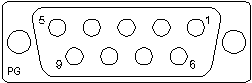
Figure 9
| EGA Adapter | |||
| 9-Pin D-type Female Connector (figure 9) | |||
|
Pin |
Signal |
Pin |
Signal |
|
1 |
GND |
6 |
Secondary Green / Intensity |
|
2 |
Secondary Red |
7 |
Secondary Blue / Mono Video |
|
3 |
Primary Red |
8 |
Horizontal Drive |
|
4 |
Primary Green |
9 |
Vertical Drive |
|
5 |
Primary Blue | ||
| VGA Adapter | |||
| 15-Pin HDD-Type Female Connector (figure 10) | |||
|
Pin |
Signal |
Pin |
Signal |
|
1 |
Red Video |
9 |
[KEY] |
|
2 |
Green Video |
10 |
Sync GND |
|
3 |
Blue Video |
11 |
Monitor ID - Bit 1 |
|
4 |
Monitor ID - Bit 2 |
12 |
Monitor ID - Bit 0 |
|
5 |
GND |
13 |
Horizontal Sync |
|
6 |
Red GND |
14 |
Vertical Sync |
|
7 |
Green GND |
15 |
N/C (Reserved) |
|
8 |
Blue GND | ||

Figure 10
Most Twisted Pair networks will use (EIA) T568A or T568B assignments.
| T568A RJ45 pin assignments (Figure 11) | ||
|
Pin |
Pair |
Colour (PRIMARY/trace) |
|
1 |
3 |
WHITE/green |
|
2 |
3 |
GREEN/white |
|
3 |
2 |
WHITE/orange |
|
4 |
1 |
BLUE/white |
|
5 |
1 |
WHITE/blue |
|
6 |
2 |
ORANGE/white |
|
7 |
4 |
WHITE/brown |
|
8 |
4 |
BROWN/white |

Figure 11
| T568B (aka 258a) RJ45 pin assignments (Figure 11) | ||
|
Pin |
Pair |
Colour (PRIMARY/trace) |
|
1 |
2 |
WHITE/orange |
|
2 |
2 |
ORANGE/white |
|
3 |
3 |
WHITE/green |
|
4 |
1 |
BLUE/white |
|
5 |
1 |
WHITE/blue |
|
6 |
3 |
GREEN/white |
|
7 |
4 |
WHITE/brown |
|
8 |
4 |
BROWN/white |
A Cross-Over jumper can be made by terminating one end of a cable as T568A and the other as T568B (i.e. crossing pairs 2 & 3) – Useful for ‘daisy-chaining’ hubs and back-to-back PC links.
|
10BaseT
Cross-Over Cable pin assignments |
||
| End A | ó | End B |
| 1 | ó | 3 |
| 2 | ó | 6 |
| 3 | ó | 1 |
| 6 | ó | 2 |
Common Modem to UK Telephone Socket
|
Typical
Hayes Compatible Modem Lead (US Source) |
||
| BT
Line Plug (BT431a or 631a) |
ó | RJ11Plug (4/6 or 6/6) |
| 1 | ó | n/c |
| 2 | ó | 3 |
| 3 | ó | 2 |
| 4 | ó | 5 |
| 5 | ó | 4 |
| 6 | ó | n/c |

Figure 12
Note: The plugs illustrated are the BT 631a and RJ11 (6/6) Line Plugs. The more common BT 431a and RJ11 (4/6) plugs are identical apart from the fact that Pins 1 and 6 are omitted; making the first and last usable connections Pin 2 and 5.
|
Typical
UK Modem Lead (e.g. Pace) |
||
| BT
Line Plug (BT431a or 631a) |
ó | RJ11Plug (4/6 or 6/6) |
| 1 | ó | n/c |
| 2 | ó | 5 |
| 3 | ó | 4 |
| 4 | ó | 3 |
| 5 | ó | 2 |
| 6 | ó | n/c |